- 您现在的位置:买卖IC网 > Sheet目录3832 > AT87C52X2-3CSUM (Atmel)IC 8051 MCU 8K OTP 40MHZ 40DIP
9
TS8xCx2X2
4184I–8051–02/08
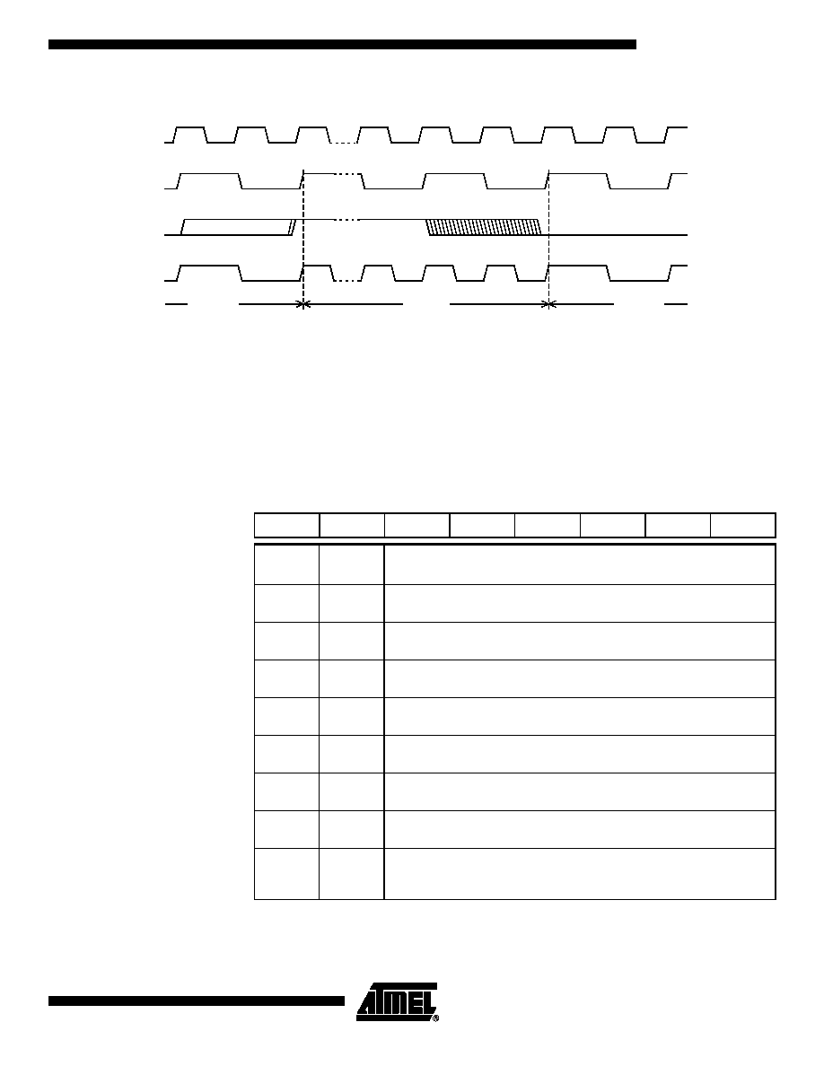
Figure 2. Mode Switching Waveforms
The X2 bit in the CKCON register (See Table 3.) allows to switch from 12 clock cycles
per instruction to 6 clock cycles and vice versa. At reset, the standard speed is activated
(STD mode). Setting this bit activates the X2 feature (X2 mode).
Note:
In order to prevent any incorrect operation while operating in X2 mode, user must be
aware that all peripherals using clock frequency as time reference (UART, timers) will
have their time reference divided by two. For example a free running timer generating an
interrupt every 20 ms will then generate an interrupt every 10 ms. UART with 4800 baud
rate will have 9600 baud rate.
Table 3. CKCON Register
CKCON - Clock Control Register (8Fh)
Reset Value = XXXX XXX0b
Not bit addressable
For further details on the X2 feature, please refer to ANM072 available on the web
(http://www.atmel.com)
XTAL1:2
XTAL1
CPU clock
X2 bit
X2 Mode
STD Mode
7
6
5
4
3
2
1
0
-
X2
Bit
Number
Bit
Mnemonic Description
7
-
Reserved
The value read from this bit is indeterminate. Do not set this bit.
6
-
Reserved
The value read from this bit is indeterminate. Do not set this bit.
5
-
Reserved
The value read from this bit is indeterminate. Do not set this bit.
4
-
Reserved
The value read from this bit is indeterminate. Do not set this bit.
3
-
Reserved
The value read from this bit is indeterminate. Do not set this bit.
2
-
Reserved
The value read from this bit is indeterminate. Do not set this bit.
1
-
Reserved
The value read from this bit is indeterminate. Do not set this bit.
0
X2
CPU and peripheral clock bit
Clear to select 12 clock periods per machine cycle (STD mode, FOSC=FXTAL/2).
Set to select 6 clock periods per machine cycle (X2 mode, FOSC=FXTAL).
发布紧急采购,3分钟左右您将得到回复。
相关PDF资料
PIC16C924-04/L
IC MCU OTP 4KX14 LCD DVR 68PLCC
PIC16F767-I/SO
IC PIC MCU FLASH 8KX14 28SOIC
PIC24FJ64GA310-I/PF
MCU 16BIT 64KB FLASH 100TQFP
DSPIC33FJ64GP202-E/MM
IC DSPIC MCU/DSP 64K 28-QFN
PIC16F876A-I/ML
IC MCU FLASH 8KX14 A/D 28QFN
PIC16F876A-I/SO
IC MCU FLASH 8KX14 EE 28SOIC
PIC16F876A-I/SP
IC MCU FLASH 8KX14 EE 28DIP
AT87C51RD2-3CSUM
IC 8051 MCU 64K OTP 40MHZ 40DIP
相关代理商/技术参数
AT87C52X2-3CSUV
功能描述:8位微控制器 -MCU Microcontroller
RoHS:否 制造商:Silicon Labs 核心:8051 处理器系列:C8051F39x 数据总线宽度:8 bit 最大时钟频率:50 MHz 程序存储器大小:16 KB 数据 RAM 大小:1 KB 片上 ADC:Yes 工作电源电压:1.8 V to 3.6 V 工作温度范围:- 40 C to + 105 C 封装 / 箱体:QFN-20 安装风格:SMD/SMT
AT87C52X2-RLRUM
功能描述:8位微控制器 -MCU 0.5um RoHS:否 制造商:Silicon Labs 核心:8051 处理器系列:C8051F39x 数据总线宽度:8 bit 最大时钟频率:50 MHz 程序存储器大小:16 KB 数据 RAM 大小:1 KB 片上 ADC:Yes 工作电源电压:1.8 V to 3.6 V 工作温度范围:- 40 C to + 105 C 封装 / 箱体:QFN-20 安装风格:SMD/SMT
AT87C52X2-RLTUL
功能描述:8位微控制器 -MCU C72X2C52 0.5m OTP RoHS:否 制造商:Silicon Labs 核心:8051 处理器系列:C8051F39x 数据总线宽度:8 bit 最大时钟频率:50 MHz 程序存储器大小:16 KB 数据 RAM 大小:1 KB 片上 ADC:Yes 工作电源电压:1.8 V to 3.6 V 工作温度范围:- 40 C to + 105 C 封装 / 箱体:QFN-20 安装风格:SMD/SMT
AT87C52X2-RLTUM
功能描述:8位微控制器 -MCU C72X2 C52 0.5 m X 2 OTP 0.5 NV RoHS:否 制造商:Silicon Labs 核心:8051 处理器系列:C8051F39x 数据总线宽度:8 bit 最大时钟频率:50 MHz 程序存储器大小:16 KB 数据 RAM 大小:1 KB 片上 ADC:Yes 工作电源电压:1.8 V to 3.6 V 工作温度范围:- 40 C to + 105 C 封装 / 箱体:QFN-20 安装风格:SMD/SMT
AT87C52X2-RLTUV
制造商:ATMEL 制造商全称:ATMEL Corporation 功能描述:8-bit Microcontroller 8 Kbytes ROM/OTP, ROMless
AT87C52X2-SLRUL
功能描述:8位微控制器 -MCU Microcontroller RoHS:否 制造商:Silicon Labs 核心:8051 处理器系列:C8051F39x 数据总线宽度:8 bit 最大时钟频率:50 MHz 程序存储器大小:16 KB 数据 RAM 大小:1 KB 片上 ADC:Yes 工作电源电压:1.8 V to 3.6 V 工作温度范围:- 40 C to + 105 C 封装 / 箱体:QFN-20 安装风格:SMD/SMT
AT87C52X2-SLRUM
功能描述:8位微控制器 -MCU Microcontroller RoHS:否 制造商:Silicon Labs 核心:8051 处理器系列:C8051F39x 数据总线宽度:8 bit 最大时钟频率:50 MHz 程序存储器大小:16 KB 数据 RAM 大小:1 KB 片上 ADC:Yes 工作电源电压:1.8 V to 3.6 V 工作温度范围:- 40 C to + 105 C 封装 / 箱体:QFN-20 安装风格:SMD/SMT
AT87C52X2-SLSUL
功能描述:8位微控制器 -MCU OTP C52/8K 40MHZ 3V COM RoHS:否 制造商:Silicon Labs 核心:8051 处理器系列:C8051F39x 数据总线宽度:8 bit 最大时钟频率:50 MHz 程序存储器大小:16 KB 数据 RAM 大小:1 KB 片上 ADC:Yes 工作电源电压:1.8 V to 3.6 V 工作温度范围:- 40 C to + 105 C 封装 / 箱体:QFN-20 安装风格:SMD/SMT